
Why the Hopper Lift Mechanism Is the Critical Safety Node
(Note: All numerical values provided in this article—including rope diameters, drum wall thicknesses, safety factors, and inspection intervals—are illustrative examples. Always verify exact specifications against the mixer’s original equipment manufacturer (OEM) manual and applicable local regulatory standards.)
In diesel concrete mixers utilizing wire-rope hoist systems, the hopper lift mechanism is the core system of the batching process. It constantly counteracts gravity, friction, and dynamic shock loads. Evaluating this system requires defining engineering standards, examining physical hardware, and identifying common failure modes to maintain a safe and productive job site.
Key Components: Gear Drive, Drum, Rope, Hopper, and Brake
Structural rigidity and reliable torque transfer are foundational requirements for any lift system. The physical integrity of the lifting frame and the drive components cannot be compromised. This assembly relies on a heavy-duty gear drive, a winding drum, a wire rope (commonly 10 mm or 0.39 in), the hopper, and an electromagnetic brake. For example, the drum in mid-sized models may be manufactured with a wall thickness of 2.75–3.75 mm (0.11–0.15 in), providing the necessary structural stiffness to prevent deformation under heavy, repeated loads.
When these core components fatigue, the consequences can lead to equipment damage or safety hazards. If a gear tooth fails under load or the drum warps due to inadequate wall thickness, the wire rope can spool unevenly, leading to binding. A structural failure here does not just halt production; it can result in an uncontrolled hopper descent, creating a significant safety risk for the crew.
How Drum Speed and Drive Design Affect Lift Safety
Operating guidelines specify optimal speeds to maintain concrete homogeneity and ensure efficient cycle times. The gear transmission typically ensures the hoist drum stays at a consistent speed, such as an illustrative 30 r/min in small to medium-scale models. This rotational consistency directly supports example productivity rates of around 10 m³/h (353 ft³/h). The drive design is tailored to handle this continuous throughput without overheating or slipping.
If the drive mechanism is poorly maintained or the speed fluctuates, mechanical jerks occur during the upward lift. A stable, controlled lift prevents dynamic shock loads from transferring into the cable and causing premature wear. Ensuring the drive system operates smoothly keeps the load path stable and minimizes unnecessary stress on the hoist components.
Main Failure Modes in Hopper Lifting Systems
Engineering safety protocols require anticipating worst-case scenarios in high-stress environments. The primary failure points in hopper lifting systems include wire rope failure due to hidden fatigue, brake slippage from worn pads, and upper limit switch malfunctions. In diesel-powered units, continuous engine vibration can accelerate mechanical wear, causing hoist mounts, sheave pins, and brake linkages to loosen over time. Operators must regularly inspect these fasteners. Furthermore, fuel handling and exhaust heat require careful management near the lifting frame.
When a limit switch fails, the motor continues operating without positional feedback, potentially driving the hopper assembly into the upper frame and snapping the rope. Identifying precursors to failure before the system yields is critical. Because the reliability of the hopper lift degrades through continuous mechanical stress and environmental exposure, proactive component monitoring is an essential practice for preventing structural failure.
How to Calculate the Wire Rope Safety Factor
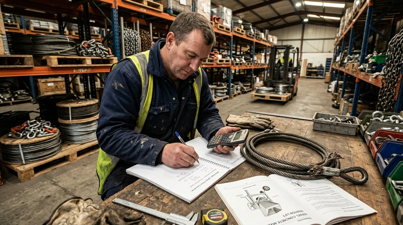
Accurate calculation of the wire rope safety factor ensures the cable is mathematically rated for the applied load. This requires accounting for the base weight of the lifting components, the material weight, and the dynamic forces at play during a rapid lift.
Engineering Definition of Safety Factor
In hoisting mechanics, the safety factor is defined mathematically as the rope’s certified minimum breaking force divided by the maximum static tension applied to it. This precise ratio dictates operational limits.
While a wire rope is a complex helix of individual steel wires that must share the load equally, safety calculations rely on the manufacturer’s certified aggregate strength rather than the sum of individual wire strengths. When individual wires break under bending fatigue or rust, the rope’s overall breaking force decreases, reducing the safety factor below acceptable limits. If this ratio is not calculated accurately based on real-world weights and current rope conditions, the system risks overloading.
How Load, Hopper Weight, and Machine Weight Affect Rope
Stress
Standards dictate that all forces acting on the cable must be accounted for in the load path. Beyond the hopper and material, the overall machine weight and its anchoring stability play a crucial role. If the mixer chassis is improperly leveled or inadequately anchored, the entire unit can become unstable during a lift. While a shifting chassis is primarily a severe tipping hazard, it can also misalign the routing sheaves, which subsequently introduces dynamic stress spikes into the rope.
As an illustrative example for a specific mid-sized model, the load path consists of the hopper assembly (e.g., weighing 350 kg or 772 lb) and a single batch of material (roughly 165 L or about 400 kg / 881 lb). Lifting this combined weight generates significant stress. In this scenario, the maximum static tension on a standard 10 mm (0.39 in) wire rope when fully loaded reaches approximately 750 kgf (7.35 kN). Load management issues happen when operators overfill the hopper or when wet, dense sand exceeds standard weight estimates, spiking that static tension far beyond design parameters.
Why Material Hoisting Requires a 5:1 Safety Factor
While general lifting equipment might legally operate on a safety factor ranging from 4 to 8, many material hoisting standards (such as ASME B30.2, ISO 4309, or FEM 1.001, depending on the jurisdiction) recommend a minimum 5:1 safety factor.
For the illustrative 750 kgf (7.35 kN) load, a 5:1 factor means the wire rope’s minimum breaking force must be ≥3,750 kgf (36.7 kN) upon installation.
| Specification Metric | Value / Threshold | Imperial Equivalent | Notes |
|---|---|---|---|
| Rope Diameter | 10 mm | 0.39 in | Standard lifting cable size |
| Max Static Tension | 750 kgf (7.35 kN) | 1,653 lbf | Based on full 165L hopper batch |
| Required Safety Factor | 5:1 | 5:1 | Common standard for material hoists |
| Min. Breaking Force | 3,750 kgf (36.7 kN) | 8,267 lbf | Must be verified via manufacturer spec |
| Design Lifespan | Tracked via usage | Tracked via usage | Monitor lifting cycles, operating hours, and environmental exposure |
Ignoring this 5:1 rule is unsafe; dynamic shock loads from sudden braking or diesel engine vibrations can easily double the momentary tension. Over-engineering the rope strength absorbs those unpredictable dynamic forces. The safety factor diminishes with wear, corrosion, and fatigue cycles, making regular calculation and inspection mandatory.
Wire Rope Wear Characteristics to Inspect
Because steel cables degrade over time despite substantial safety margins, monitoring wear characteristics is essential for predicting and preventing failure. Industry best practices typically mandate a visual inspection every 14 days, with a comprehensive teardown check if the machine sits idle for over a month.
Broken Wires, Abrasion, Corrosion, and Kinking
The engineering standard for wire rope integrity focuses heavily on surface degradation and structural deformation. The wire rope is subjected to constant, aggressive friction against the steel drum and the routing sheaves, with the outer layer of wires taking the majority of this mechanical wear.
Common wear patterns include broken wires from repeated bending fatigue, severe abrasion on the outer strands from dragging, internal corrosion from water and cement slurry exposure, and kinking from improper spooling. When kinking occurs, the rope’s core is permanently deformed, altering how the load is distributed across the strands. Spotting these wear patterns early prevents localized stress concentrations, which are often the starting points for a cable failure.
When Rejection Rules Require Rope Replacement
Replacement protocols follow strict regulatory thresholds, which vary by region and manufacturer. As an example, depending on the regulatory body, a wire rope must often be rejected if the total number of visible broken wires exceeds 10% within any length equal to eight times the rope diameter. For a 10 mm (0.39 in) rope, this requires inspecting an 80 mm (3.15 in) span. Additionally, a common standard requires immediate replacement if a single outer wire is worn down to one-third of its original diameter.
These 10% and one-third reduction rules are examples; always consult specific ISO 4309 or local guidelines. These rejection rules supersede any timeline or warranty period. Ignoring established broken wire or diameter reduction rules risks an unpredictable loss of tensile strength.
How to Identify Unsafe Rope Wear Early
Identifying unsafe wear early requires a highly disciplined routine. Standard operating procedures mandate daily checks on both wear and lubrication. Applying a penetrating wire rope lubricant—such as a light oil or specialized asphaltic coating as specified by the manufacturer—reduces internal friction between the individual wires as they bend around the hoist drum.
Internal corrosion can remain hidden until the rope fails under a surprisingly light load. By carefully running a gloved hand over the rope (only after proper Lockout/Tagout [LOTO] procedures have been applied and the machine is fully de-energized) to feel for burrs, operators can catch early signs of strand failure. Rope degradation accelerates exponentially once outer strands begin failing, making strict adherence to rejection thresholds the only reliable way to prevent failures under load.
Brake and Limit Protection Reliability
The braking system and limit switches serve as the control center of the hoisting operation, ensuring the load can be stopped and held precisely. Understanding their failure modes is critical for operator safety.
How the Brake Controls the Winding Drum
Hoisting brakes are designed for fail-safe operation—meaning if power is lost, the brake engages automatically and instantly. The system features a specialized brake motor that drives the winding drum through a heavy-duty reducer.
For models using manual discharge control, the responsiveness of this brake is paramount. The response time directly determines whether a fully loaded hopper stops precisely at the discharge chute or drifts past it. Performing a basic brake engagement-distance check—verifying that the load stops within the exact allowable drift tolerance specified by the manufacturer—ensures the brake is functioning correctly. A highly responsive brake provides total, predictable control over a suspended load.
Brake Base, Arm, Shoe, and Spring Inspection Points
Standard maintenance protocols require continuous verification of stopping power. The electromagnetic braking device comprises a solid base, a brake arm, a friction brake shoe, an electromagnetic core, an armature, and a heavy-duty main spring.
| Brake Component | Common Failure Mode | Inspection Metric | Required Action |
|---|---|---|---|
| Main Spring | Loss of tension / fatigue | Measure uncompressed length | Replace if below spec |
| Brake Shoe | Friction material worn | Pad thickness | Replace before metal-on-metal |
| Armature | Sticking due to dust | Smooth engagement sound | Clean and lubricate housing |
| Electromagnet | Coil short / burnout | Resistance (Ohms) check | Rewind or replace coil |
Issues usually originate in the main spring losing tension over time or the brake shoe wearing down past its safe friction limits. If the armature gets stuck due to concrete dust or debris, the brake will not release or engage properly. Inspecting these specific points ensures the fail-safe mechanism clamps down securely when power is cut.
Why Dual Upper Limit Switches Improve Safety
Upper limit protection is critical for preventing over-winding, which can cause severe equipment damage. Redundant safety circuits are standard for heavy hoists. In this setup, the upper limit position is often equipped with dual limit switches.
The first switch triggers the power-off braking to complete the discharge sequence safely. If that primary switch fails—which can happen due to dirt, moisture, or mechanical impact—the second limit switch provides essential backup protection to kill the power immediately. This dual setup prevents the motor from over-traveling and damaging the hopper tracks. Braking redundancy serves as essential secondary protection when primary circuits fail, ensuring the hopper never exceeds its structural limits.
Maintenance and Safety Decision Criteria
Strict daily maintenance protocols and clear operational criteria are vital for translating engineering specifications into job site safety. Establishing these guidelines ensures safe operational zones, proper component upkeep, and timely equipment decommissioning.
Daily and Periodic Maintenance Requirements
The operational standard for longevity is built on consistent, scheduled maintenance. This requires daily checks on cable lubrication, drum alignment, and brake responsiveness, alongside mandatory 14-day visual inspections.
If the mixer has been sitting idle for over a month, a full comprehensive check is required before it ever lifts a hopper. Lax maintenance leads to accelerated, unseen wear—like a dry rope experiencing severe internal abrasion or a brake shoe glazing over. A consistent periodic routine transforms unpredictable breakdowns into scheduled, manageable service intervals.
Safety Pins, Chains, No-Standing Zones, and Drum Wall Checks
Physical safety zone standards are strict. A suspended hopper is a severe crush hazard. Therefore, rules dictate that when the hopper is elevated, it is strictly forbidden for personnel to stand or walk underneath it.
For maintenance, the hopper must be raised to its highest point and securely locked using a physical safety pin or suspended with heavy-duty chains. Additionally, technicians must check the drum wall thickness, ensuring it remains within safe operational ranges. Relying solely on the electromagnetic brake while working under the hopper is unsafe. Using physical pins and enforcing no-standing zones ensures absolute isolation from mechanical failure risks.
Final Criteria for Safe Operation or Rope Replacement
Rather than relying solely on reactive replacement thresholds, operational safety is actively engineered through a concrete pre-lift checklist. Before operations begin, crews should verify the following consolidated criteria:
- Lockout/Tagout (LOTO): Verify LOTO procedures are fully applied before any hands-on maintenance or teardown checks.
- Safety Factor Verification: Confirm the wire rope safety factor meets OEM and local regulatory standards for the specific load and current rope condition.
- Rope Inspection: Conduct a visual rope span inspection for broken wires, abrasion, kinking, and internal corrosion, adhering strictly to rejection rules.
- Brake Testing: Perform a brake drift test under load to ensure the hopper holds its position within the manufacturer’s exact allowable tolerances.
- Physical Safeguards: Engage physical safety pins or heavy-duty chains whenever the hopper is elevated for maintenance, and strictly enforce no-standing zones.
Adhering to this comprehensive checklist, alongside strict load limits and timely component replacement, ensures the lift mechanism operates safely and reliably.
Further reading:
- Diesel Concrete Mixer
Key Takeaways
- Verify rope diameter, allowable load, brake settings, and inspection intervals against the OEM manual before servicing any diesel concrete mixer hoist.
- Inspect the wire rope before operation for broken wires, corrosion, kinks, flattening, diameter loss, and uneven spooling, and replace it when damage exceeds the manufacturer’s limits.
- Keep the drum, gear drive, sheaves, and frame aligned and free from deformation because poor spooling can concentrate stress and accelerate cable failure.
- Test the brake and upper limit switch regularly, since brake slippage or loss of travel control can lead to uncontrolled hopper movement.
- Control shock loading by maintaining smooth drive operation and avoiding jerky starts, sudden stops, or overfilled hopper lifts.
- Check hoist mounts, pins, brake linkages, and fasteners more frequently on diesel-powered mixers because vibration can loosen critical parts over time.
Frequently Asked QuestionsWhy is the hopper lift mechanism a major safety concern in diesel concrete mixers?
It supports the loaded hopper against gravity while handling vibration, friction, and shock loads. If the rope, drum, gear drive, brake, or limit switch fails, the hopper may descend uncontrollably or damage the mixer frame.
What safety factor should be used for a mixer hopper wire rope?
The required safety factor depends on the OEM design, rated hopper load, local lifting regulations, and duty cycle. Always confirm the specified rope diameter, grade, and allowable load in the manufacturer’s manual before replacing or modifying the hoist system.
What are common signs of wire rope wear on a concrete mixer hopper?
Look for broken wires, kinks, birdcaging, corrosion, flattened strands, uneven spooling, heat damage, and diameter reduction. Any visible deformation or rapid wear pattern should trigger immediate inspection and possible rope replacement.
How does drum condition affect hopper lift safety?
A worn, cracked, or deformed drum can cause poor rope winding, side loading, and localized cable stress. The drum surface, flanges, bearings, and wall integrity should be checked regularly to prevent rope crushing or jamming.
Why is brake reliability critical in diesel concrete mixers?
The brake must hold the hopper securely when lifting stops or power is interrupted. Worn brake pads, weak springs, oil contamination, or poor adjustment can cause slippage and create a serious drop hazard.
Media Contact
Company Name: Max Machinery
Email: Send Email
Country: China
Website: https://www.max-machinery.com/