
Deyang, Sichuan, China – September 28, 2026
1. Overview of the Problem
Flat blank width — sometimes called developed width or unfolded width — is the dimension of the strip before it enters the roll forming line. It is calculated from the finished cross-section by “unrolling” every bend around its neutral axis.
This is not a forming-process error in the way that roll gap misalignment or pass-schedule mistakes are. It is a design-stage error that gets baked into the tooling before the first coil is ever loaded. That makes it more dangerous: the mill can run perfectly, the rolls can be perfectly aligned, and the part will still be out of tolerance because the tooling itself was cut to the wrong flat width.
Key distinction: Roll misalignment produces inconsistent parts from a correctly designed tool. Incorrect flat blank width produces consistently wrong parts from an incorrectly designed tool — every piece is wrong the same way.
2. Root Causes
2.1 Wrong Neutral Axis Assumption
Every bend in sheet metal stretches the outer surface and compresses the inner surface. Somewhere between the two lies a neutral axis that neither stretches nor compresses. Many blank width calculations still assume the neutral axis sits at exactly 50% of material thickness. In practice, the neutral axis shifts toward the inner radius as the bend gets tighter.
2.2 K-Factor Selected From the Wrong Table
The K-factor is the fraction of material thickness at which the neutral axis actually sits. K-factor tables built for press-brake air bending are commonly reused for roll forming, where the strain pattern is different. Applying a press-brake K-factor introduces a systematic width error.
2.3 Material Thickness and Hardness Not Accounted For
Bend allowance is sensitive to both material thickness and yield strength. A blank width calculated for a mild steel coil will not hold for a higher-strength or galvanized coil with different work-hardening behavior.
2.4 Ignoring Springback in the Width Model
Blank width formulas that only account for geometric bend allowance will be increasingly wrong as thickness or hardness increases. The finished included angle opens slightly after forming, causing dimensions to drift.
2.5 Cumulative Rounding Across Multiple Bends
Profiles with many bends compound small per-bend errors. A 0.1 mm error per bend across twelve bends becomes a 1.2 mm total width error — enough to push a finished profile outside tolerance.
3. Neutral Axis and Bend Allowance Diagram
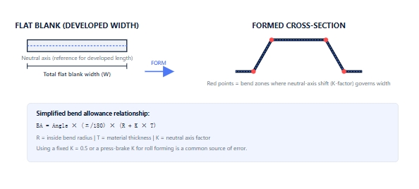
Fig. 1 — Relationship between the flat blank’s neutral axis and bend allowance at each forming station.
4. Error Severity Reference Table
|
Error Source |
Typical Width Deviation |
Severity |
Detection Point |
|
Fixed K = 0.5 assumption |
0.15 – 0.4 mm per bend |
Medium |
First-article inspection |
|
Press-brake K-factor reuse |
0.2 – 0.6 mm per bend |
High |
Overall width check |
|
Springback not modeled |
0.1 – 0.5 mm per bend |
Medium |
Angle inspection |
|
Material grade change |
0.3 – 1.0+ mm total |
High |
Coil changeover run |
5. Downstream Consequences
- · Leg or flange height out of tolerance — short or long blanks show up as undersized or oversized legs.
- · Hem or interlock misalignment — self-mating profiles fail to close correctly when width error compounds.
- · Excess or insufficient trim allowance — edge trimming either scraps material or leaves burred edges.
- · Tooling rework cost — correcting blank-width errors usually means re-cutting multiple roll stations.
- · Delayed customer acceptance — first-article samples fail sign-off, pushing back project delivery.
6. Engineering Solutions From XC XiongChang
Accurate flat blank width calculation is a design discipline. Our process treats it as a verified input, not an assumption.
01
Material-Specific K-Factor Data
We maintain empirically validated K-factor references specifically for roll forming — not adapted from press-brake tables.
02
Springback-Corrected Modeling
Our workflow incorporates springback compensation into the developed width calculation before any tooling is cut.
03
First-Article Verification
Every new tool set is validated with full-profile measurement to catch cumulative bend error before customer handover.
Get Your Cross-Section Design Reviewed
Send us your profile drawing — our engineers will verify blank width and tooling design before you commit to production.
Tel: +86 18280009773Email: info@xcrollformer.com
7. Why Roll Forming Manufacturers Choose XC XiongChang
Sichuan Xiongchang Technology Co., Ltd. (XC XiongChang) has spent over 20 years designing and manufacturing cold roll forming equipment.
- · Proven Expertise & Innovation — over 20 years of specialized experience with an in-house R&D center.
- · Built for Performance & Longevity — machines engineered for durability, operating at higher speeds with precision.
- · Commitment to Customer Success — 24/7 customer support with comprehensive after-sales service and global trade experience.
If your production line is showing consistent dimensional drift, the issue is very likely upstream. Our team can review your calculations and recommend corrections.

About Us
As an established expert in the field, XC (Xiongchang) provides integrated roll forming solutions. Our portfolio encompasses core production machines for roofing, flooring, doors, and structural components, as well as the complete auxiliary line equipment essential for efficient operation.
Media Contact
Company Name: Sichuan Xiongchang Technology Co., Ltd.
Contact Person: Media Relations
Email: Send Email
Country: China
Website: https://www.xcrollformer.com/