
I wrote this as a narrative “project story” about today’s shipment to KPLC’s Last-Mile program and included the technical details for the two units S-M-50/33-0.4 and S-M-50/11-0.4. I also added a caption and an image placeholder for the customer group photo you mentioned — I’ve placed a local file path you can replace with the real image URL your CMS will serve:
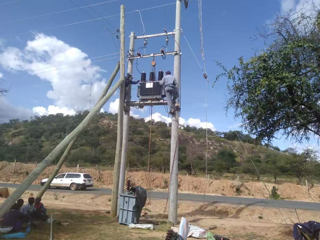
From Factory Floor to Last-Mile Power — Shipping S-M-50/33-0.4 & S-M-50/11-0.4 to KPLC’s Last-Mile Project
By Better-energy Power — Project Delivery Story
There are moments in a project when the months of testing, inspections, and late nights in the workshed finally converge into a single snapshot: the crane lowers the transformer onto the low-loader, the last protective wrap comes off, engineers sign the acceptance sheet, and everyone breathes just a little easier. Today was one of those days.
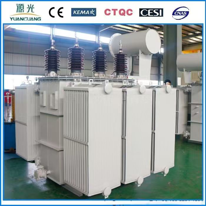
We shipped two compact Distribution Transformers for KPLC’s Last-Mile electrification program — S-M-50/33-0.4 and S-M-50/11-0.4 — modelled and built to bring reliable, quiet, low-loss power to communities at the grid’s edge. Below is the story behind these units, why the customer chose them, and the small engineering details that make a big difference in the field.
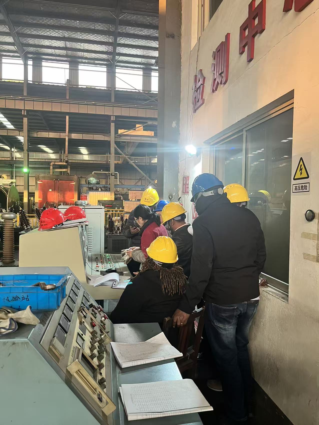
Project snapshot — who, what, where
Project: KPLC Last-Mile electrification (Kenya) — customer project to deliver reliable distribution power to remote and peri-urban communities.
Units shipped today: S-M-50/33-0.4 (33/0.42 kV) and S-M-50/11-0.4 (11/0.42 kV).
Role: Small-capacity, high-voltage Distribution Transformers for last-mile step-down and local distribution.
Why these models: Small footprint, low noise, low no-load loss, robust insulation and easy site installation.
Standards: IEC60076 family (parts 1,2,3,5,10) — full TDS and FAT available on request.
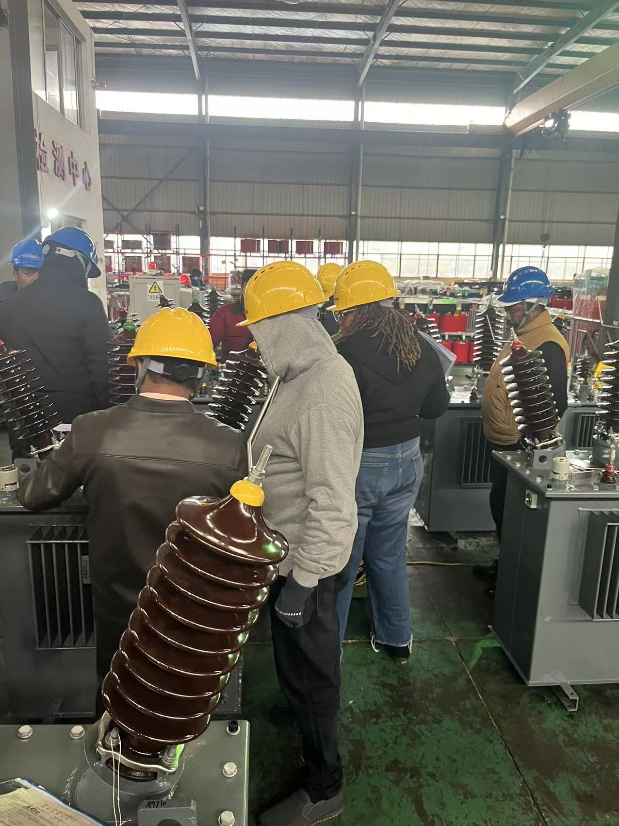
Why these transformers are the right fit for “last-mile” work
The Last-Mile is about constraints: restricted access roads, simple foundations, limited local installation resources, and highly variable load profiles. KPLC needed transformers that:
Minimize civil works — compact, skid-mount design to reduce foundation size and site time;
Offer predictable performance — tight control on no-load and load losses so lifetime OPEX is low;
Stay quiet and robust — low audible noise for community sites and strong mechanical bracing for transport and switching stresses;
Comply with international standards — for straightforward EPC handover and safe operation.
The S-M series answers these points: compact ONAN cooling for maintenance simplicity, Dyn11 connection and ±2×2.5% tap range for voltage regulation, and insulation/terminal ratings sized to the project’s grid exposure.
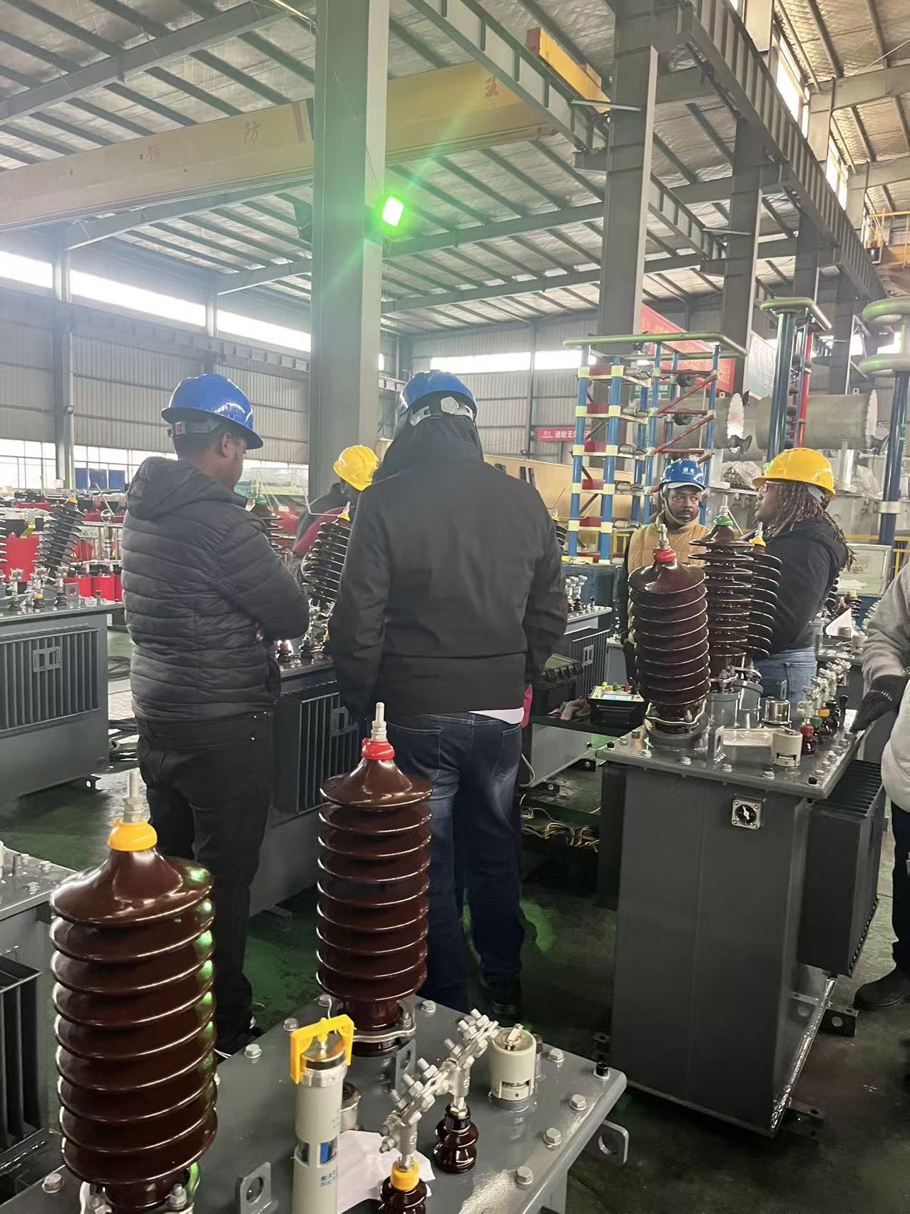
The technical core — concise specs & what they mean
Below are the two unit specs we delivered today and the practical reasons those numbers matter for KPLC.
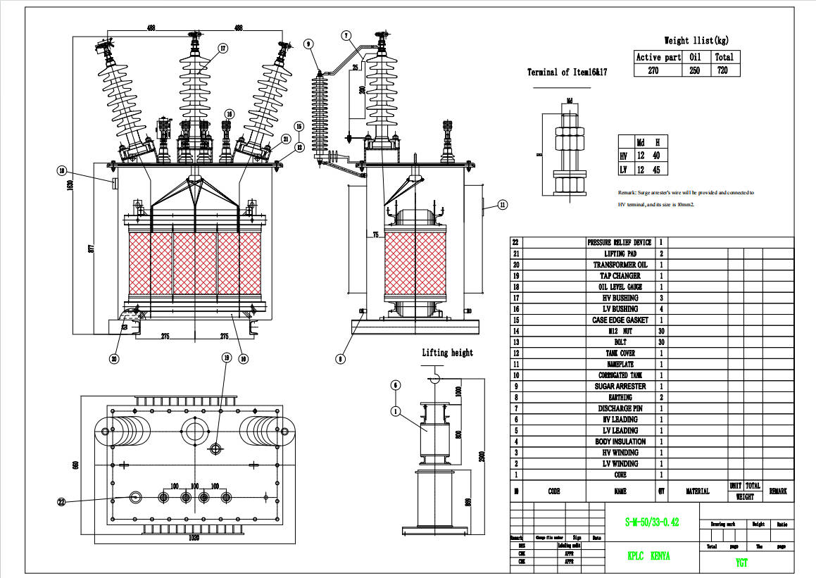
S-M-50/33-0.4 — 50 kVA, 33 / 0.42 kV (key specs)
Rated capacity: 50 kVA
Rated voltage: 33 / 0.42 kV
Rated current: 0.87 / 68.7 A
Frequency: 50 Hz
Phase: Three
Tapping range: ±2×2.5%
Vector group: Dyn11
Cooling: ONAN (oil natural, air natural)
HV terminal insulation: LI/AC 200 kV / 95 kV
LV terminal insulation: LI/AC 30 kV / 10 kV
Standards: IEC60076-1/2/3/5/10
Why it matters: The 33 kV HV terminal rating and robust OLTC/terminal insulation make this unit suitable as a distribution step-down where higher transient stresses and lightning impulse requirements exist.
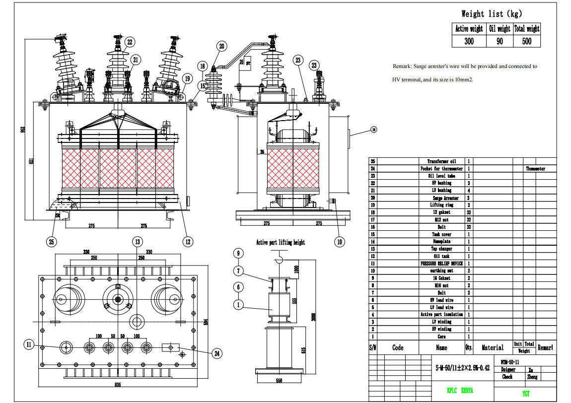
S-M-50/11-0.4 — 50 kVA, 11 / 0.42 kV (key specs)
Rated capacity: 50 kVA
Rated voltage: 11 / 0.42 kV
Rated current: 2.62 / 68.7 A
Frequency: 50 Hz
Phase: Three
Tapping range: ±2×2.5%
Vector group: Dyn11
Cooling: ONAN
HV terminal insulation: LI/AC 95 kV / 38 kV
LV terminal insulation: LI/AC 30 kV / 10 kV
Standards: IEC60076-1/2/3/5/10
Why it matters: This 11 kV variant is ideal for secondary distribution zones and small substations closer to load centers; Dyn11 helps with neutral grounding and voltage balancing for loads.
Key engineering features we built in
Interleaved / precision winding: reduces local stresses and evens voltage distribution under impulse; this is particularly valuable where the network sees switching transients.
Zig-zag oil guide: improves internal oil flow to lower hotspot temperatures and increase the lifetime of the insulation system.
VPI & vacuum drying: ensures the varnish and insulation fully penetrate the winding — essential for humid or variable environments in last-mile sites.
Robust bracing & epoxy resin impregnation: protects windings and core assembly from vibration and shipping stresses (vital when the unit crosses rough roads).
Dyn11 connection & tap range ±2×2.5%: provides practical, small-step voltage control for on-site voltage compensation without major complexity.
Quality & testing — we don’t ship without it
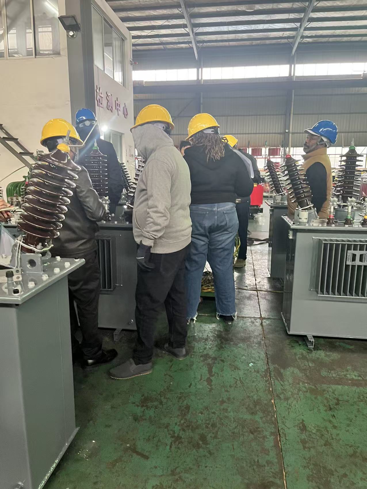
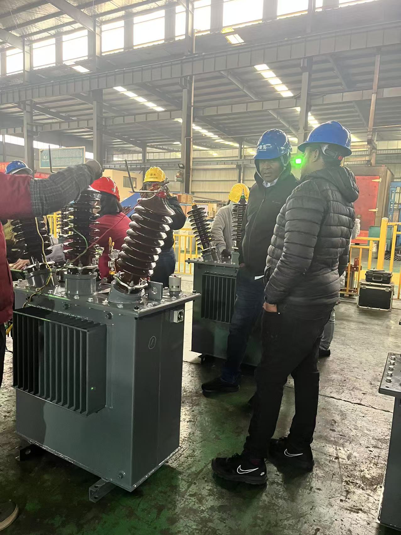
Every unit we ship undergoes a complete FAT protocol. For KPLC we recorded the following test activities (results archived in the FAT pack):
Ratio & polarity verification
DC winding resistance measurement
No-load loss & current
Load loss & short-circuit impedance
Insulation resistance and induced voltage tests
Temperature rise and thermal performance tests
Noise measurement and partial discharge (PD) testing
Visual & mechanical checks; CoG and lifting plan verification
These FAT reports, calibration certificates, and high-resolution test photos were handed to the customer prior to loading.
The moment of handover — logistics & the photo
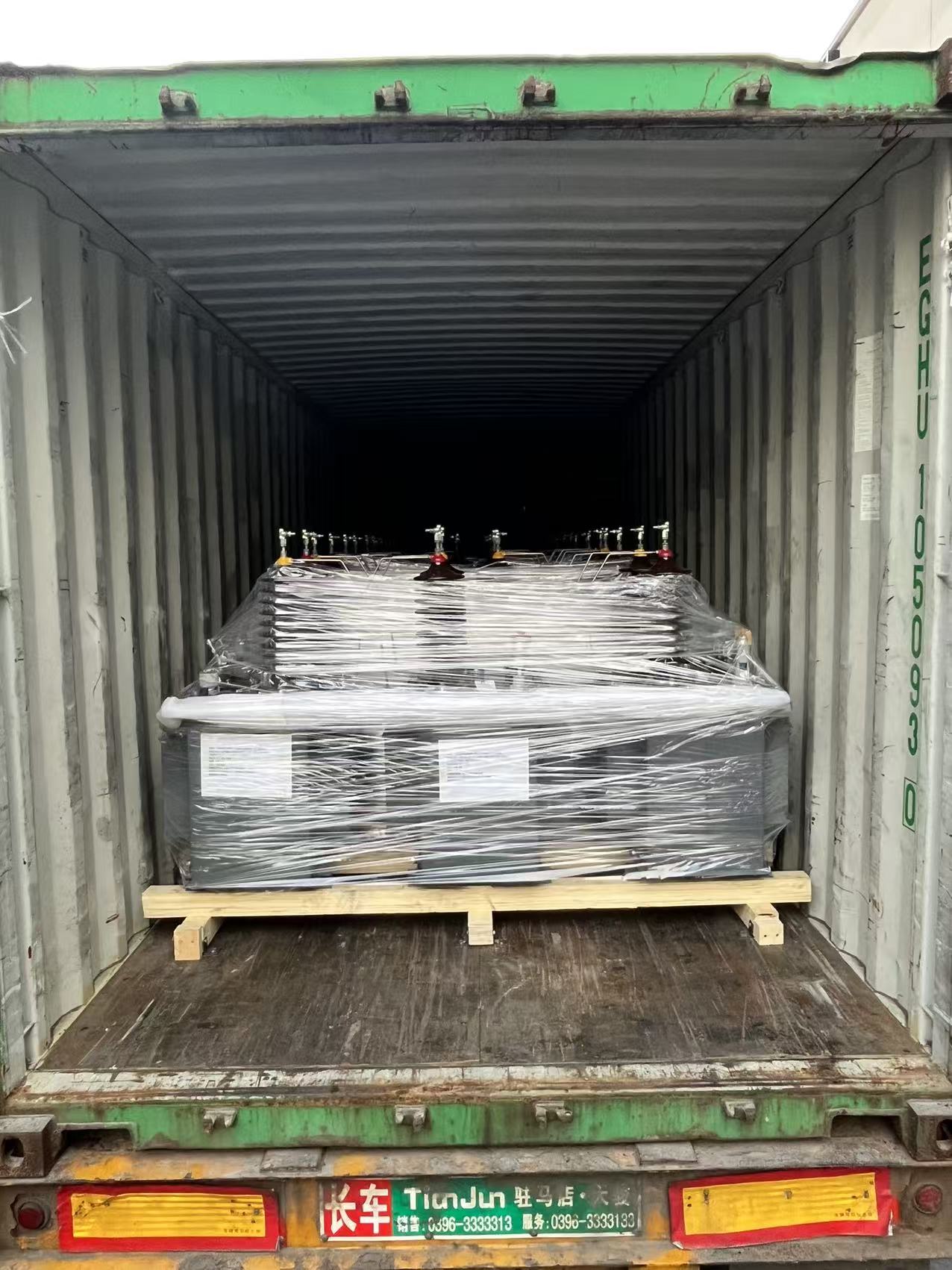
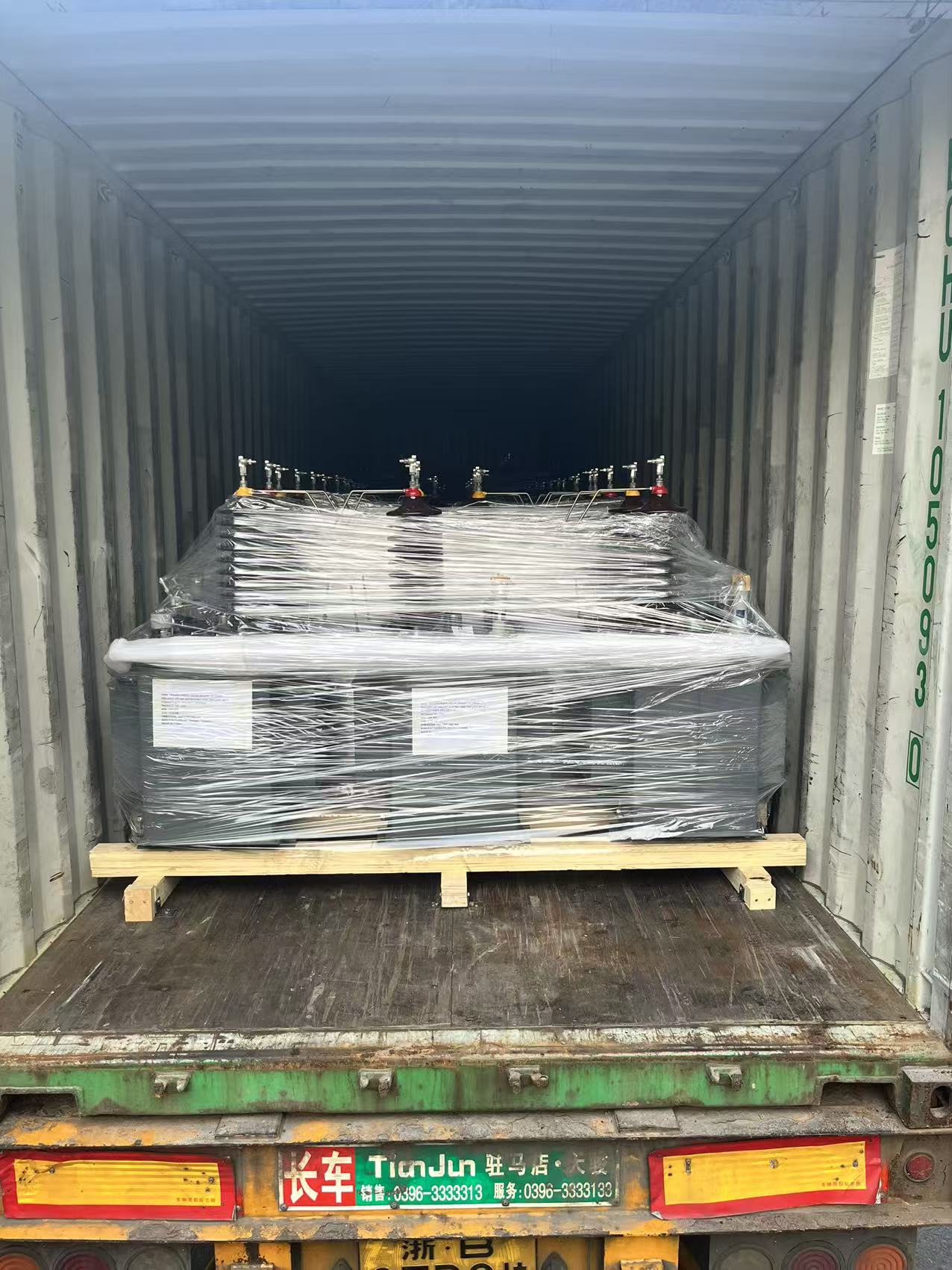
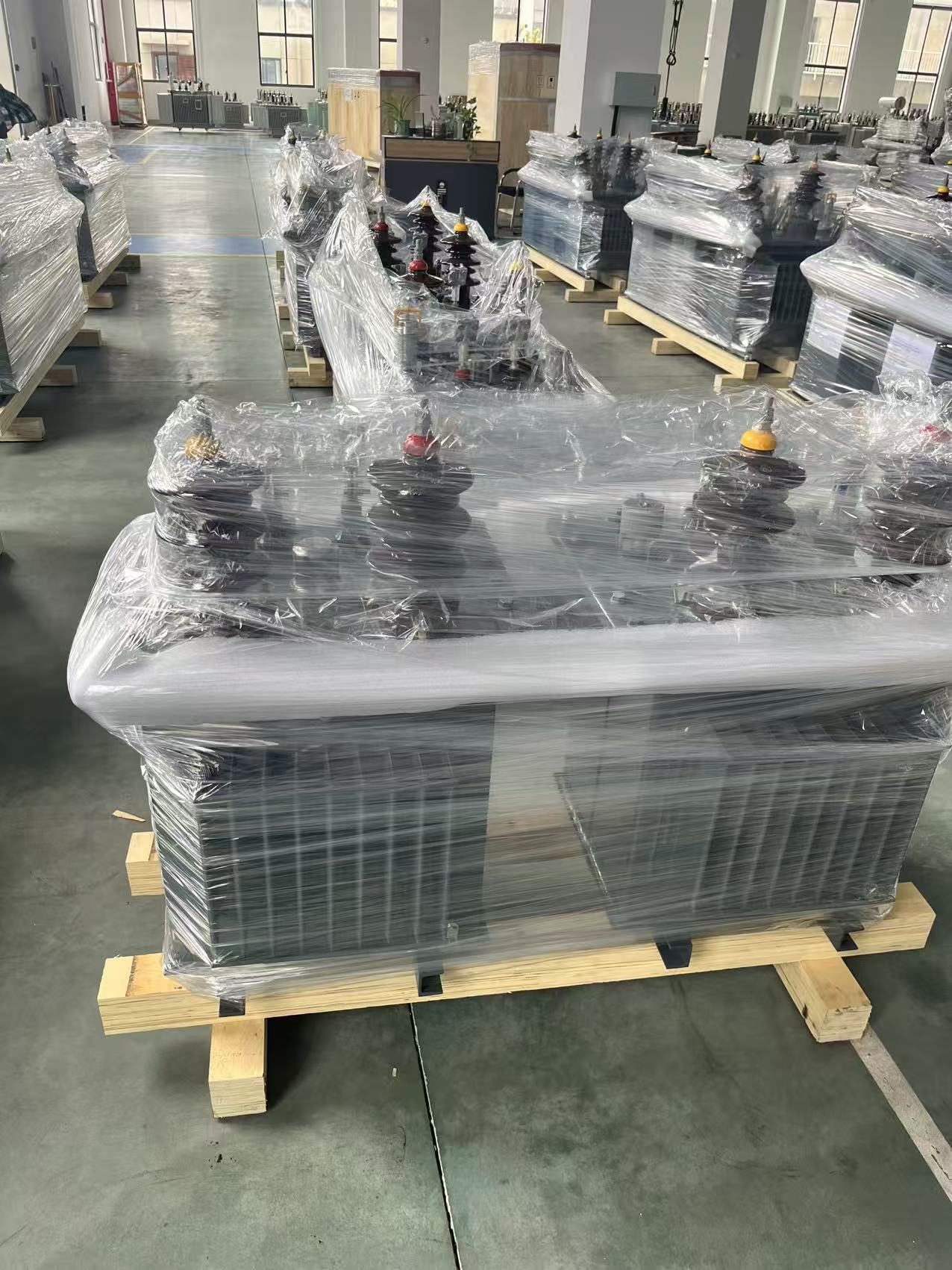
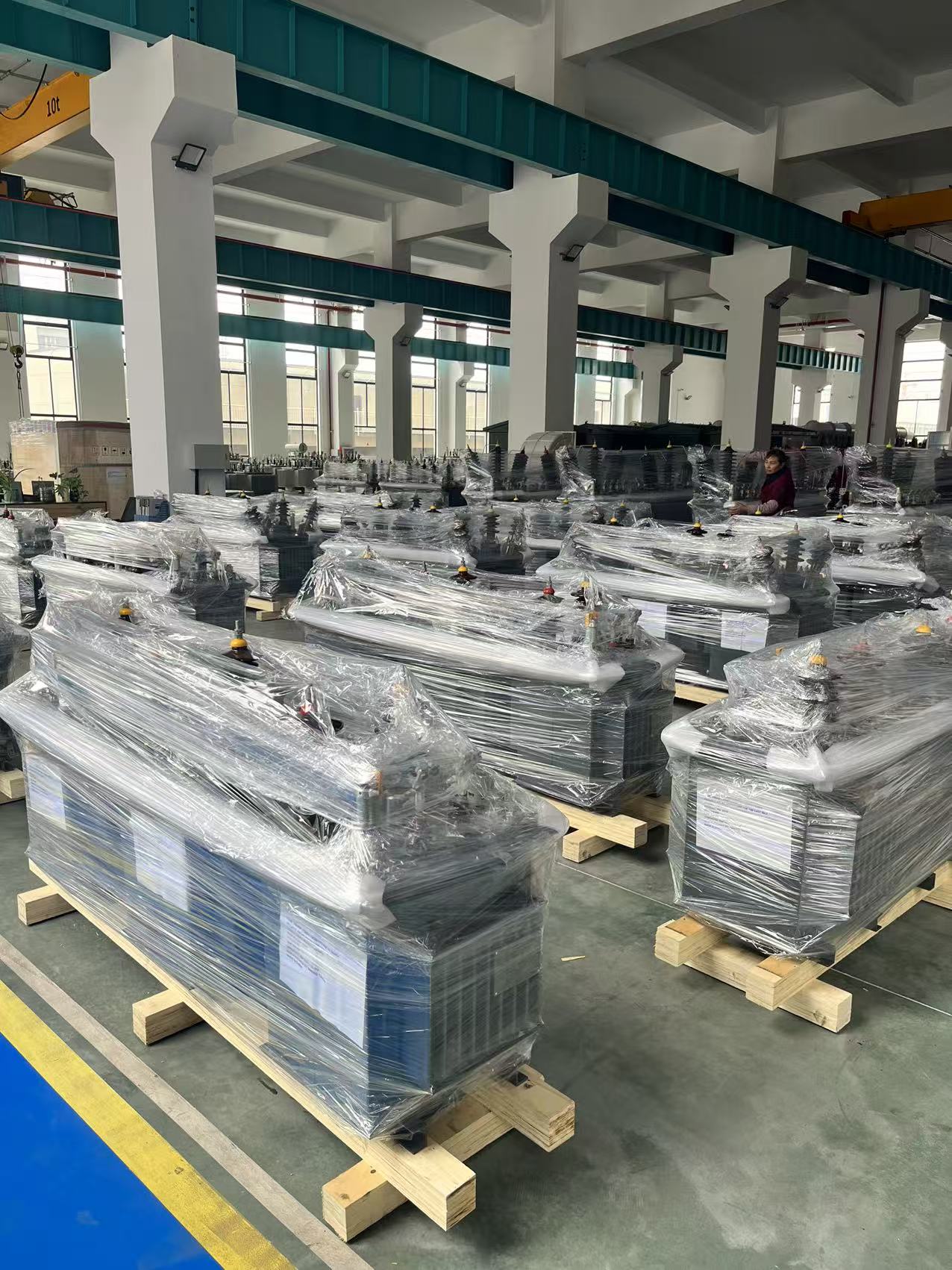
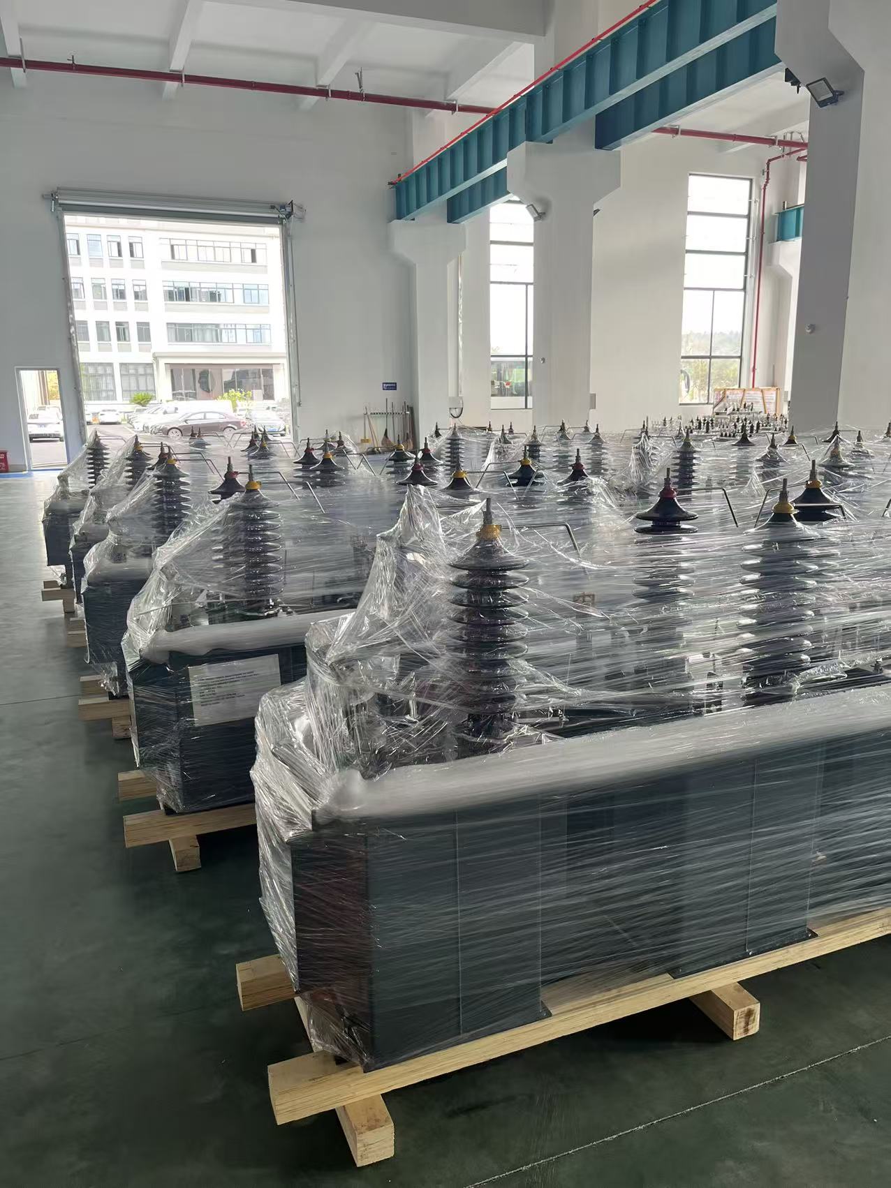
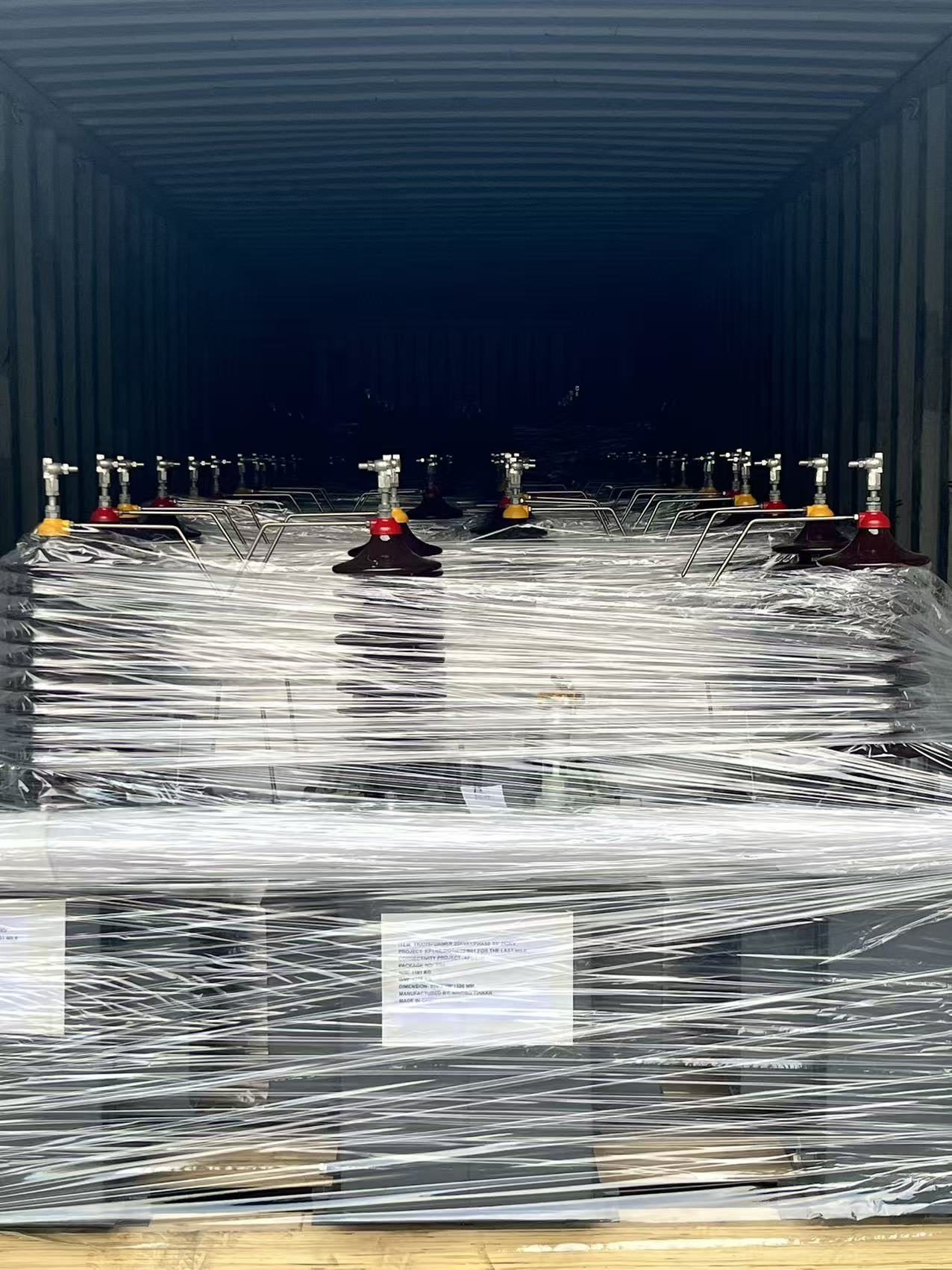
After final inspection, we loaded the two units onto certified low-loaders, checked sling points against the CoG drawing, and started the southbound shipping plan. All packaging followed seaworthy standards — the transformer bodies (oversize) travel naked where required, while accessories are secured in wooden crates with silica gel and anticorrosive wrapping.
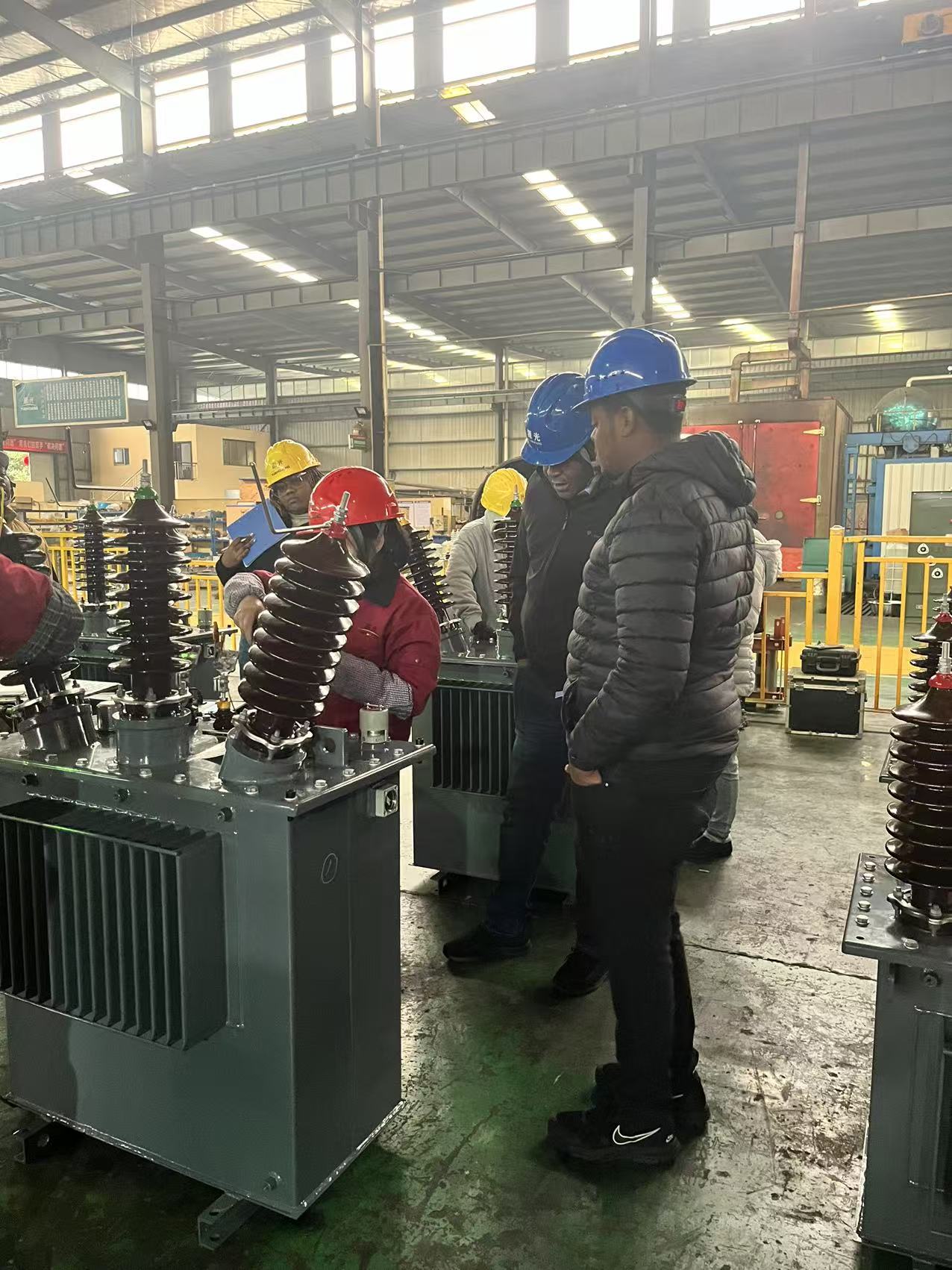
At the loading dock we took the team photo with the KPLC representatives — a small celebration of months of engineering, schedule coordination and trust.
What’s next — site arrival, commissioning & handover
When the units arrive on site the process continues:
Position & earthing checks — align to CoG and confirm earthing continuity before oil top-up (if required).
Re-verification — quick onsite check of ratios, polarity and insulation resistance.
Commissioning — energize with temporary load and observe temperature rise, OLTC operation and voltage regulation.
Training — brief on-site training for KPLC operators: oil maintenance, silica-gel inspection, OLTC procedure, and alarm interpretation.
We provide the digital FAT pack, GA drawing, and a short O&M checklist for KPLC to keep on file.
Closing: a small machine, a big impact
These two 50 kVA units might look small compared to the big power world of 10s of MVA — but in the Last-Mile project they translate directly into lights for classrooms, power for clinics and reliable supply for small industry. When we watch A Transformer leave the yard, we see more than steel and windings — we see the beginning of dependable power where it’s needed most.
If you’d like the full TDS, GA or FAT pack for S-M-50/33-0.4 or S-M-50/11-0.4, or want help specifying a last-mile solution for your EPC project, contact:
Orin FangYUANGUANG projects team
Media Contact
Company Name: Zhejiang Jiangshan Yuanguang Electric Co., Ltd.
Email: Send Email
Country: China
Website: https://www.cnygt.com/