
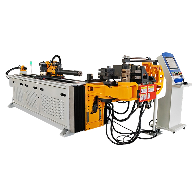
Zhangjiagang, Jiangsu, China – November 19, 2026
Choosing a cnc pipe bender starts with the finished component: its material, cross section, bend radii and assembly interfaces. Diameter capacity alone cannot establish whether a machine will produce a complex tube successfully. The selection needs to cover the forming tools and the movement of the entire workpiece through every bend. A useful specification connects those requirements to a repeatable setup and an agreed method of inspecting the finished part.
Define the tube before comparing machines
Record the actual outside dimensions, wall thickness and material grade. Include the material condition when it affects forming. A nominal pipe designation and an exact tube outside diameter describe different things, so the quotation needs the dimensions that the tools will contact. For welded stock, add the seam location requirements and any restrictions on its orientation through a bend. The drawing also needs an unambiguous radius convention. Centerline radius describes the radius followed by the tube centerline; inside radius describes a different surface. Confusing them changes the required tooling and the finished geometry. State the bend angle, straight lengths and rotation between successive bends using a consistent datum system.
Tolerances deserve individual treatment. An angle tolerance, a minimum remaining wall and a final connection position are separate acceptance requirements. Prioritize the dimensions that control assembly instead of applying one tight tolerance to every feature. That distinction helps the equipment review concentrate on functional fit.
Match the tooling to the forming task
Rotary draw bending uses a bend die to establish the radius while a clamp holds the tube against it. Other tooling supports the material as it moves. Thin walls and demanding radii can require internal mandrel support and a wiper die to manage deformation near the bend. These components work together; choosing the drive system does not complete the tooling specification.
Clamping length can become the limiting factor on a compact component. A short straight between two bends leaves less room for a conventional clamp. A contoured clamp may grip an earlier bend, but its geometry belongs to that particular component. This makes the distance between bends commercially relevant even when the machine has sufficient nominal diameter capacity.
Surface requirements also affect gripping. A visible architectural part may permit fewer clamp marks than a concealed industrial tube. Decide where marks are acceptable and how they will be judged. Increasing clamp pressure without reviewing tooling contact can exchange one defect for another.
Check the complete bending sequence
A machine can reach each specified angle and still struggle with the complete part. After the first bend, the workpiece occupies more space around the bending head. Feeding or rotating it for a later operation can bring an earlier leg close to the frame, tooling or floor.
Simulation helps review these movements before a trial. The machine model, installed dies and tube geometry need to represent the intended setup. A clear screen image is useful for reviewing a route, but physical trials remain necessary to establish material behavior and finished dimensions. Heshun offers automatic configurations including multi-die and left-right bending equipment. The practical selection question is which motion or tooling change removes a specific obstruction in the proposed sequence. Extra axes have value when their functions solve a drawing requirement; an axis count alone does not describe that value.
Evaluate springback through a controlled trial
The tube relaxes after the bending force is released. Its final angle can therefore differ from the programmed angle. Material properties and tooling settings affect this response, so a universal correction factor is a poor basis for qualifying a new component.
Use representative production stock for the trial and record the setup with the measured results. When the material changes, review whether the established compensation remains suitable. Otherwise a program that was successful on one lot can be reused without the conditions that made it successful.
A cnc pipe bender should make the successful setup understandable and recoverable. Record the tooling identification, stock specification and compensation alongside the program revision. The useful output of a trial is a repeatable manufacturing method, together with acceptable samples.
Compare production performance on equal terms
Distinguish bending motion time from the complete production cycle. Loading, unloading and inspection consume time even when axis movements are automatic. A quotation based on the bending sequence alone cannot describe how many accepted parts the cell will deliver during a shift. For mixed production, changeover deserves separate observation. Include tool installation and the time to approve the first acceptable component. A faster automatic cycle may have limited value if frequent tooling changes consume much of the available production window.
Use the same component and acceptance rules when comparing proposed systems. Record the trial quantity, observed rejects and operator involvement. Avoid treating an isolated demonstration cycle as a sustained output commitment. Production planning needs the operating conditions that produced the result.
Specify the handover around future use
The purchase scope should identify the supplied tools, software functions and sample programs. Clarify which fixtures belong to the machine and which are specific to a component. This reduces ambiguity when another part is introduced or a worn tool needs replacement.
Operator training should follow the actual production tasks, including setup recovery and normal fault handling. Maintenance access also matters: a compact layout can become inconvenient when routine service requires moving surrounding equipment. Review the machine footprint together with its service space and the swept envelope of the largest workpiece.
For a cnc pipe bender used across several product families, nominate representative parts rather than only the easiest drawing. Include the tightest radius and the most awkward spatial shape when they are relevant. The resulting trial scope gives the production team a clearer basis for accepting the investment.
Use geometry ratios to make the enquiry more precise
Two simple ratios help describe a round tube application. Wall factor is outside diameter divided by wall thickness. Bend ratio is centerline radius divided by outside diameter. They organize the discussion of geometry without establishing a guaranteed forming limit.
For a hypothetical 30 mm tube with a 1.5 mm wall and a 60 mm centerline radius, the wall factor is 20 and the bend ratio is 2. Changing the wall to 1 mm increases the wall factor to 30, although the outside diameter remains unchanged. The enquiry now describes a different support problem that a diameter-only capacity comparison would hide.
Keep these calculations alongside the complete drawing. They do not account for the material condition, available clamp length or the interaction of successive bends. Their value is in exposing differences between applications before the supplier recommends a particular model or tool set.
A quotation can then separate the equipment configuration from the application trial. Identify which component features determine tool selection and which need physical measurement. This makes a later specification change easier to assess because the reason for the original selection remains explicit.
Prepare a drawing led equipment discussion
A useful enquiry includes a dimensioned drawing, material specification and expected batch pattern. Add the critical acceptance dimensions and explain how the tube connects to the next assembly. With that information, machine capacity, tooling and the production sequence can be assessed together. To discuss the configuration for a complex tube family, submit the drawings through https://hsformer.com/ and identify the part that presents the greatest forming or clearance challenge.
About Us
Zhangjiagang Heshun Machinery Manufacturing Co., Ltd., founded in 2001, occupies a total area of 60,000 square meters with total assets of CNY 130 million. The company employs over 50 staff members, including engineering technicians with intermediate or higher professional titles (28% of total workforce). It boasts one doctoral R&D team and holds one National First (Set) Major Technical Equipment Program certification and one provincial-level research project.
As a specialized manufacturer of metal tube processing machinery, Heshun Machinery focuses on R&D and manufacturing of metal tube forming equipment. The company has successfully developed internationally advanced tube bending machines and laser cutting machine software.
Its main products include five major series with over 180 models:
CNC Tube Bending Machines、Chamfering Machines、Tube Cutting Machines、Tube End Forming Machines、Automated Intelligent Production Lines All equipment features technical performance reaching domestic leading and internationally advanced levels. The company prioritizes product quality and technological sophistication, having developed more than 30 new products and obtained over 30 patents since its establishment. Recognized as a National High-Tech Enterprise in 2018, Heshun obtained ISO 9001 Quality Management System Certification in 2015.
Media Contact
Company Name: Zhangjiagang Heshun Machinery Manufacturing Co., Ltd
Contact Person: Media Relations
Email: Send Email
Country: China
Website: https://hsformer.com/