
Hangzhou, Zhejiang, China – November 19, 2026
Honestly, picking a bandpass filter from any “top 10” list isn’t about crowning one universal champ—it’s about finding the right fit for your optical setup. You know how a filter can work great on a lab bench, isolating that narrow wavelength like a dream? Then you put it in a warm, shaky instrument and suddenly it’s not so great. Things like center wavelength, bandwidth, peak transmission, blocking range, angle of incidence, and even operating temperature all play a role. It’s the little details that get you. A few nanometers here or there and the signal you’re measuring can shift, sometimes in ways you really don’t expect.So, I was looking at MarketsandMarkets’ Optical Filter Market report—it does a solid job of tracking demand by filter type and application sector. You can really see how these components show up everywhere, from imaging to sensing to communications. That big-picture context is useful and all, but at the end of the day, it’s no substitute for checking the actual datasheet or running your own application test. So if you’re looking at Ir Bandpass Filters, don’t just glance at the specs. You’ll want to dig into the wavelength range, the actual transmission curve, what substrate it’s on, and the temperature limits. And here’s something people often overlook: ask how the filter behaves when light hits it at an angle. Because if you mount it tilted, that passband can shift on you. In real-world use, it’s way better to compare measured curves under conditions that match your setup rather than trusting the headline numbers. A catalog part number isn’t proof it’ll work. Alright, so this guide runs through ten different options—looking at their specs and what they’re probably best used for. I’ll also point out where the official specs don’t quite tell the whole story. There are trade-offs that are super easy to overlook, and honestly, no ranking is going to fit every setup perfectly. So before you buy anything, double-check that it actually works with your source, detector, and environment.
 Define Bandpass Specs: Center Frequency, 3 dB Bandwidth, and Q = f₀/BW
A bandpass filter’s center frequency, f₀, marks the middle of its passband. Its 3 dB bandwidth is the distance between the lower and upper frequencies where output power falls to half its peak level. IEC Electropedia defines quality factor, Q, as the ratio of resonant frequency to bandwidth. The calculation is simple: Q = f₀/BW. Small detail, big effect.
For example, a filter centered at 915 MHz with a 30 MHz 3 dB bandwidth has Q = 30.5. If its passband edges are 900 and 930 MHz, the arithmetic midpoint is 915 MHz. These are calculated values, not a performance claim from a test report. In a real specification, check whether the stated bandwidth is measured at the 3 dB points, and whether tolerances shift the center frequency or edges. I still double-check this: a narrow bandwidth may improve selectivity, but it can also make tuning more sensitive. A wider passband gives more room for signal variation, though nearby interference may slip through. Define the required frequencies and measurement conditions before comparing filters.
Compare 10 Filter Technologies by Q, Insertion Loss, Size, and Power
Choosing among 10 filter technologies starts with the signal, not a specification sheet. Quality factor (Q) describes selectivity, while insertion loss shows how much useful signal disappears. Size and power handling matter just as much in a compact instrument or a warm optical assembly.
Thin-film interference filters can offer low loss and strong rejection, but performance may shift with angle.Fabry–Pérot etalons provide narrow passbands; they can be sensitive to alignment.Absorptive glass filters are simple and compact, though their passbands may be broader.Angle-tuned and linear-variable filters trade fixed installation for adjustment.Grating-based designs separate wavelengths physically, often needing more optical space.Fiber Bragg filters are compact in fiber systems, but packaging affects their use.Plasmonic filters can be very small, with loss as a concern.Metasurface filters offer design flexibility, though real-world power limits need checking.Resonant-cavity filters can deliver high Q, but may demand careful fabrication.
Infrared Bandpass Filters should be compared at the intended wavelength, temperature, beam angle, and power density. A high-Q choice may reject nearby wavelengths well, yet deliver too little signal. Small is not free. Ask for measured insertion loss and damage-threshold data under conditions close to your setup. I have seen a neat bench result become less convincing once the beam warmed the mount; the test conditions matter.
Review LC, Crystal, Ceramic, SAW, BAW, Cavity, and Waveguide Filters
Bandpass Filters pass a chosen frequency range while reducing signals above and below it. The right design depends on center frequency, bandwidth, insertion loss, power, and available space. An LC filter uses inductors and capacitors, making it practical when tuning flexibility and moderate cost matter. Its response can shift with component tolerances and temperature, so a bench measurement may differ from a simulation.Crystal filters suit narrow bands and stable frequencies, but their operating range is less flexible. Ceramic filters offer compact construction and useful selectivity for many receiver designs, though performance varies by material and layout. SAW filters are small and effective at higher frequencies, but insertion loss and temperature sensitivity deserve attention. BAW filters can provide strong selectivity in compact packages at still higher frequencies. Small does not mean simple.Cavity filters can handle substantial power with low loss and sharp rejection, yet they need room and careful mechanical tuning. Waveguide filters are useful at microwave frequencies, especially where power handling and low loss are priorities; their size and fabrication precision can become constraints. Compare measured passband shape, rejection, group delay, and temperature behavior under real operating conditions. One specification is easy to overlook: connector and fixture effects can distort a quick test. The “best” filter is sometimes only the least awkward compromise.
Top Bandpass Filter Technologies: Typical Practical Frequency Ranges
Compare the approximate operating-frequency ranges of common bandpass filter technologies. The logarithmic scale makes ranges spanning several orders of magnitude easier to compare.
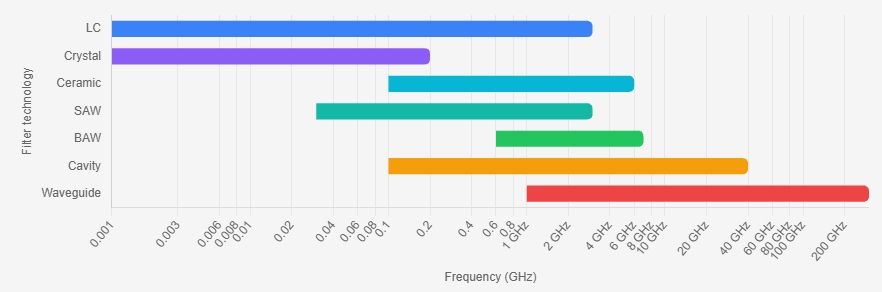
Ranges are indicative, not absolute limits; actual frequency coverage depends on filter design, bandwidth, materials, and implementation. Frequency is shown in GHz on a logarithmic scale.
Match Bands: 2.4 GHz ISM (2400–2483.5 MHz) and 5G n78 (3.3–3.8 GHz)
A Bandpass Filter should match the signal’s full operating range, not just its center frequency. The 2.4 GHz ISM window spans 2400–2483.5 MHz, while 5G n78 spans 3300–3800 MHz. 3GPP TS 38.101-1 specifies n78’s frequency range. These bands are far apart, so one conventional narrow passband cannot cover both. Choose separate filters or a designed dual-band filter. Check insertion loss, rejection outside the passband, and power handling against your radio’s requirements. Small losses matter.Tip: Measure at the antenna port. A short cable, connector, or nearby metal surface can change the result. For a 2.4 GHz device, also check interference from nearby Wi-Fi and Bluetooth signals; a filter cannot separate signals that overlap inside its passband.For n78, confirm the exact channel bandwidth and regional operating range before selecting a filter. A filter that passes all of n78 may admit more unwanted energy than a narrower design. Conversely, a tight passband can clip useful signal at the channel edges. This trade-off is easy to underestimate. Review the filter’s measured response across temperature, and test it in the final enclosure, not only on a bench.
Verify RF Performance: Insertion Loss, Return Loss, Rejection, and Power Rating
A bandpass filter can look ideal on a specification sheet and still disappoint in a real RF path. Check insertion loss at the frequencies you actually use, not only at the passband center. A reading of 1 dB means measurable signal loss; across several connected components, those decibels add up. Small losses matter. Return loss also deserves attention. Poor matching can send energy back toward the source, especially when cables or connectors differ from the test setup.Rejection describes how strongly the filter suppresses unwanted signals outside its passband. Compare the rejection curve with nearby interferers, and note the frequency range over which the figure is guaranteed. A single impressive number may describe only one point. Power rating is equally practical: confirm both average and peak limits, and consider heat buildup in a compact enclosure. Dielectric Filters can suit applications needing stable, selective filtering, but performance still depends on the chosen design and operating conditions. Specifications are useful; they are not the whole installation.Tips: Measure with calibrated equipment and suitable adapters. Record the test frequency, power level, and temperature. These details make comparisons more reliable. If readings differ from the datasheet, inspect the setup before blaming the filter. I have seen small connection changes shift results, and it is easy to overlook them.
Choose a Filter for Your Signal, Environment, and Design Constraints
A bandpass filter is not chosen by center frequency alone. Start with the signal’s occupied bandwidth, then allow room for modulation sidebands and oscillator drift. For a concrete reference, 3GPP TS 38.104 Release 17 specifies 5G NR channel bandwidths up to 100 MHz in FR1 and 400 MHz in FR2. That range shows why one filter shape cannot suit every link. A narrow crystal filter can isolate a stable, low-frequency channel; a cavity filter may suit higher power and sharper rejection. Compact ceramic or acoustic filters save space, but insertion loss and temperature drift still need checking.
The environment changes the answer. In a warm enclosure, frequency response can shift; near switching supplies, unwanted signals may land close to the passband. Check passband ripple, stopband attenuation, group delay, impedance, power handling, and operating temperature against the actual system. A steep skirt looks attractive on paper. Yet it can add loss or distort a wide signal. That trade-off is easy to underestimate.
Tips: Measure the signal at the filter input, not only at the source. Compare the measured spectrum with the filter’s datasheet, including temperature limits. Leave margin for tolerances. If the design is still uncertain, test the filter in its real enclosure; lab conditions can be kinder than the finished product.
Conclusion
Choosing among Bandpass Filters starts with understanding the key specifications: center frequency, 3 dB bandwidth, and quality factor, calculated as Q = f₀/BW. Different technologies—including LC, crystal, ceramic, SAW, BAW, cavity, and waveguide designs—offer different trade-offs in selectivity, insertion loss, physical size, and power handling. Comparing these characteristics helps narrow the options to filters suited to a particular signal and design.Frequency range and operating conditions matter just as much. For example, a filter for the 2.4 GHz ISM band (2400–2483.5 MHz) has different requirements from one designed for 5G n78 (3.3–3.8 GHz). Before making a selection, verify insertion loss, return loss, out-of-band rejection, and power rating. The right choice balances filtering performance with available space, environmental demands, and overall system constraints.
About Us
Founded in 2007, Hangzhou MULTI IR Technology Co., Ltd. is an optoelectronic technology enterprise integrating R&D, production, and sales. Its products are widely applied in aerospace, medical care, AR/VR, display imaging, photography, and other fields, steadily holding the position of the world’s largest spot supplier of optical components.
Media Contact
Company Name: HANGZHOU MULTI IR TECHNOLOGY CO., LTD.
Contact Person: Media Relations
Email: Send Email
Country: China
Website: https://www.miroptech.com/