
Shenzhen,China-November 18, 2026
What Press-Fit Pin Defects Should Be Evaluated?
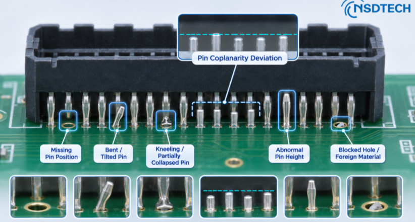
The NSDTECH Press-Fit AOI Inspection System mixes 2D vision with 3D measurement. From what’s published, it can check for things like missing pins, bent pins, kneeling pins, blocked holes, foreign material, and dimensional deviations.
But for any specific application, you’ll want to tie each defect to something you can actually see or measure—and to a clear acceptance rule.
|
Inspection target |
Question to answer during evaluation |
Validation consideration |
|
Missing pin |
Is a required terminal absent? |
Distinguish missing terminals from intentionally unpopulated positions. |
|
Bent or tilted pin |
Does the terminal deviate from its permitted position or shape? |
Include bending in different directions and confirm visibility. |
|
Kneeling or partially collapsed pin |
Has the terminal deformed during insertion? |
Confirm which parts of the deformation are accessible to inspection. |
|
Abnormal pin height |
Is the measured terminal height outside the drawing limits? |
Define the reference surface and upper and lower limits. |
|
Pin coplanarity deviation |
Do the specified pin tips fall within the permitted height range? |
Define the pin group and the calculation method. |
|
Blocked hole or foreign material |
Is an inspection area obstructed or contaminated? |
Confirm whether the relevant area remains visible at the selected process stage. |
Don’t treat every height difference as an insertion defect
A height reading doesn’t mean much on its own—you need context. Before you call a terminal “incorrectly inserted,” figure out what you’re actually measuring: exposed pin length, connector seating height, or some other accessible dimension.
Then check that measurement against the product design to make sure it really tells you something about insertion quality. And any threshold you use should come from the approved drawing or quality criteria—not just a guess.
Keep visible geometry separate from hidden connection quality
When you validate samples, you should identify both what you can detect and what the inspection can’t really see.
If a suspected defect is inside a plated through-hole or underneath an opaque connector body, ask yourself: what visible evidence actually supports this inspection call? Don’t assume an external measurement proves everything about the internal connection.
And if the quality plan calls for it, pair optical inspection with other checks—like process monitoring, electrical testing, or destructive analysis.
How to Select a Press-Fit Pin Inspection Solution1. Build an Inspection Requirement Matrix
Start with a list of requirements for each PCB and connector family.
Record:
- Connector identification and pin layout.
- Mandatory inspection items.
- Dimensional tolerances and acceptance criteria.
- Critical defects that require rejection.
- Known sources of normal production variation.
- Required inspection records and review procedures.
This matrix provides a common basis for comparing proposals and planning sample trials.
2. Match the Inspection Method to the Requirement
|
Inspection requirement |
Approach to evaluate |
Key selection question |
|
Pin presence and visible position |
2D imaging |
Can each required position be distinguished under realistic lighting and surface variation? |
|
Pin height and height consistency |
3D measurement |
Can the system measure the relevant feature with adequate repeatability near the acceptance limits? |
|
Visible shape plus dimensional checks |
Combined 2D and 3D inspection |
Can the proposed configuration cover all mandatory features? |
|
Obstructed inspection areas |
Application-specific access assessment |
Is an additional view, different process stage or complementary method required? |
The NSDTECH product page describes 2D inspection for visible features and 3D measurement for height and profile evaluation. The appropriate configuration should be confirmed using the actual board and connector geometry.
3. Review Board Handling and Measurement Access
Provide the maximum PCB dimensions, thickness, assembled weight and component heights on both sides.
Also review:
- Board support and clamping locations.
- Connector locations near board edges.
- Tall components around inspection targets.
- Access to the intended measurement surface.
- Board warpage and fixture variation.
- Product changeover requirements.
A board that fits inside a machine may still require an application review to confirm reliable access to every critical feature.
4. Evaluate Measurement Performance Against Your Tolerances
Ask for evidence that addresses the actual acceptance limits.
Useful evaluation questions include:
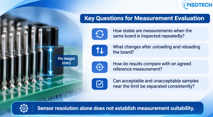
- How stable are measurements when the same board is inspected repeatedly?
- What changes after unloading and reloading the board?
- How do results compare with an agreed reference measurement?
- Can acceptable and unacceptable samples near the limit be separated consistently?
Sensor resolution alone does not establish measurement suitability.
5. Confirm Complete Inspection Cycle Time
Evaluate cycle time using a representative inspection program.
Specify whether the reported time includes board transfer, identification, positioning, data acquisition, processing, result storage and unloading. If manual review is required, assess its effect on production capacity separately.
6. Define Traceability Requirements
NSDTECH lists production data recording and MES integration capability. Before implementation, agree on the required data fields, interface and handling of communication failures.
A practical record may include board identification, recipe revision, connector location, measured values, defect category, inspection time and final disposition.
What Samples Are Needed for Press-Fit Inspection Validation?
A useful trial should include normal production variation, known defects and samples close to the acceptance limits.
Recommended Sample and Document Checklist
|
Item to provide |
Recommended information |
Purpose |
|
PCB assembly overview |
Board dimensions, thickness, weight and component heights |
Assess handling and access. |
|
Connector drawings |
Pin arrangement, pitch, nominal dimensions and tolerances |
Define inspection targets. |
|
Acceptance criteria |
Approved limits and defect classification rules |
Establish pass/fail decisions. |
|
Known-good assemblies |
Representative boards from normal production |
Evaluate normal variation and false rejects. |
|
Known-defect assemblies |
Clearly identified examples of each priority defect |
Evaluate defect detection. |
|
Near-limit samples |
Independently characterized samples around acceptance boundaries |
Assess decision stability. |
|
Defect location map |
Board ID, connector ID, pin position and confirmed condition |
Compare results with reference labels. |
|
Production requirements |
Target takt time, product mix and changeover needs |
Assess operational suitability. |
|
Data requirements |
Barcode examples, required records and interface expectations |
Plan traceability validation. |
How Many Samples Should Be Submitted?
Agree on sample quantities after reviewing the product range, defect categories and validation objective.
A small feasibility trial can help establish visibility and measurement access. A production acceptance study requires broader coverage of normal variation and enough independently verified examples to support the agreed performance assessment.
Artificially created defects should be identified as such, because they may not fully represent defects produced by the actual insertion process.
How Should the Sample Validation Be Conducted?
Step 1: Confirm the “answer key” first
Give every sample its own unique ID. Before the trial, confirm where each problem is and what the correct size values should be. If you’re not sure whether a sample is good or bad, figure that out first—before using it to judge how well the inspection system performs.
Step 2: Build the inspection setup
Use a set of samples you’ve already defined to decide which areas the system should check, what it should measure from, and where the pass/fail lines should be. If you can, keep some samples separate for final validation, so the final check includes boards that were not used to adjust the system.
Step 3: Check whether repeated checks give the same result
Check the chosen samples again and again, including taking them out and putting them back in. Look at both the measured numbers and whether the pass/fail result stays the same—especially for features that are close to the limit.
Step 4: Check whether it catches bad units and whether it wrongly rejects good ones
Don’t rely only on one overall accuracy number. Report results by problem type. Before testing, decide what counts as “one unit”: one pin, one connector, or one whole board. Useful measures include:
- Bad-unit catch rate: out of all units confirmed to be bad, how many were correctly rejected.
- Wrong-rejection rate: out of all units confirmed to be good, how many were wrongly rejected.
- Repeatability: how much the measured value changes when the same feature is measured again and again.
- Full run time: how long it takes to complete the agreed inspection sequence.
Always state the sample counts next to the results. Catching a few defects that were supplied for the test should not be presented as a guaranteed production catch rate.
Step 5: Write down what was covered and what still needs work
The evaluation report should identify:
- Which inspection items were validated.
- Sample IDs and reference classifications.
- The recipe version and acceptance limits.
- Detection and measurement results.
- Areas that cannot be inspected or are uncertain.
- Fixture or configuration changes that are needed.
- Items that still need further verification.
Frequently Asked Questions
1.Can a camera-based check by itself catch every problem with press-fit pins?It depends on what you need to check. A camera can confirm that a pin is there and in the right position. But if you need to know how tall or high something is, you need a proper way to measure size—not just a picture.
2.Can one setup work for every circuit board design?Not always. Different boards can have different pin arrangements, different connector shapes, and different pass/fail rules. So you may need different settings for different boards. When reviewing the application, include how the right setup is chosen and how it’s checked after switching from one board to another.
3.What if you don’t have any bad samples to test with?Start with drawings, boards you know work correctly, and a clear list of the problems you care about most—ranked by priority. Before you conclude anything about what problems the system can catch, agree on how you’ll get representative bad samples.
4.Can photos prove how well the inspection works?Photos can help with an early review of layout and access—whether the system can see what it needs to see. But to check whether repeated measurements give the same result, how parts are handled, how surface appearance affects the check, and how long a full inspection takes, you need real physical samples.
Discuss Your Press-Fit Pin Inspection Requirements with NSDTECH
To start an application review, share your PCB dimensions, connector drawings, target defect list, dimensional tolerances and production cycle-time requirements.
Where available, include known-good assemblies, identified defective samples and near-limit examples. These inputs help define a sample evaluation plan and assess a suitable NSDTECH Press-Fit AOI inspection solution for your production requirements.
About us
As a global intelligent equipment &material provider, NSDTECH has continued to focus on SIX major fields: Semiconductor Packaging and Testing Equipment; Semiconductor Packaging and Testing Materials; AI+Vision Inspection; Automated Testing; Intelligent Manufacturing; PCBA Auxiliary Materials since 2011 for global customers. We provide customers with cost-effective to their total solutions requirement.
Media Contact
Company Name: Shenzhen Nsdtech Technology Co., Ltd.
Contact Person: Media Relations
Email: Send Email
Country: China
Website: https://www.nsdsemi.com/