In industrial automation, analog input modules serve as the critical bridge between field sensors and control systems, converting real-world physical measurements into digital data that drives process decisions. The T8431 analog module from Rockwell Automation stands as a proven solution for engineers requiring precise, reliable data acquisition in demanding industrial environments. Yet many facilities face persistent challenges when integrating these modules with legacy systems—from compatibility uncertainties to configuration complexities that can delay commissioning and impact production uptime. This comprehensive overview addresses these concerns by examining the T8431’s technical specifications, providing step-by-step installation guidance, and exploring practical sourcing strategies for both new deployments and system upgrades. Whether you’re retrofitting aging infrastructure or designing new control architectures, understanding this module’s capabilities ensures your analog input requirements are met with confidence and precision.
What is the T8431 Analog Input Module?
The T8431 analog input module represents Rockwell International Corporation’s commitment to delivering industrial-grade signal conversion technology for complex automation environments. Designed as a precision interface device, this module transforms continuous analog signals from field instruments—such as temperature transmitters, pressure sensors, and flow meters—into digital values that programmable logic controllers can process and act upon. Within Rockwell’s broader automation ecosystem, the T8431 functions as a critical data acquisition component, bridging the gap between physical process variables and control logic execution.
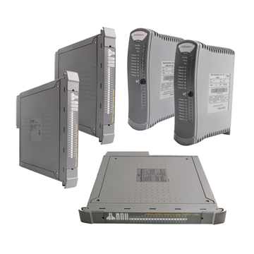
Historically, analog modules evolved from simple voltage-to-digital converters into sophisticated instruments capable of handling multiple input types with enhanced noise rejection and diagnostic capabilities. The T8431 follows this progression, offering engineers a compact solution that mounts directly into compatible control chassis alongside processors and communication modules. Its physical form factor adheres to standard industrial module dimensions, featuring removable terminal blocks for field wiring and LED status indicators for operational visibility. The module integrates seamlessly with ControlLogix and similar PLC platforms, residing on the backplane bus where it communicates scan data to the processor while drawing power from the chassis power supply. This architectural integration eliminates the need for external power sources and simplifies system design for multi-module configurations.
Detailed Technical Specifications of T8431 Electrical Characteristics
The T8431 module accepts both voltage and current input signals, accommodating standard industrial ranges including 0-10V DC, ±10V DC, 0-20mA, and 4-20mA configurations. Its 16-bit analog-to-digital converter delivers resolution sufficient for precise process control applications, with typical conversion times under 10 milliseconds per channel enabling responsive data acquisition. Channel-to-channel isolation of 250V RMS and channel-to-backplane isolation of 1500V RMS protect against ground loops and electrical interference common in industrial settings. The module employs delta-sigma conversion technology that provides inherent noise filtering, achieving accuracy within ±0.1% of full scale under stable conditions.
Environmental Specifications
Designed for harsh industrial environments, the T8431 operates reliably across temperatures ranging from 0°C to 60°C, with storage ratings extending from -40°C to 85°C. It withstands relative humidity up to 95% non-condensing and tolerates vibration levels meeting IEC 60068-2-6 standards for transportation and operational shock. The module carries UL Class I Division 2 certification for hazardous location deployment and CE marking for European compliance. Typical power consumption remains below 4 watts, minimizing heat dissipation concerns in densely populated control cabinets with adequate ventilation.
Compatibility and Integration
The T8431 mounts in standard 1756 ControlLogix chassis and compatible backplanes, communicating via the ControlLogix backplane at 1 Gbit/s data rates. Firmware compatibility requires ControlLogix processors running revision 16 or later, with full functionality available in Studio 5000 Logix Designer version 20 and above. Each module occupies a single chassis slot and supports up to eight differential input channels with individual addressing through the controller’s I/O configuration tree. The module utilizes standard Rockwell EDS files for automatic device recognition, simplifying integration into existing control architectures without custom driver development.
Installation and Wiring Procedures Step-by-Step Mounting Guide
Begin installation by powering down the ControlLogix chassis and verifying all connected equipment is de-energized. Select a chassis slot based on I/O addressing requirements and thermal considerations—avoid placing analog modules directly adjacent to high-heat components like power supplies. Align the T8431 module with the chassis slot guides, ensuring the backplane connector faces rearward. Apply firm, even pressure until the module seats completely and the retention latch clicks into place. Verify the module sits flush with adjacent modules without gaps. Connect the chassis ground bus to earth ground using 12 AWG wire or larger, maintaining less than 1 ohm resistance to minimize electrical noise. Install the removable terminal block by aligning its keyed connector with the module’s front terminals and pressing until it locks securely. Before applying power, visually confirm all backplane connections are secure and no foreign objects obstruct ventilation paths.
Wiring Configurations
Use shielded twisted-pair cable for all analog signal connections, with shield grounded at the module end only to prevent ground loops. For 4-20mA current inputs, connect the positive sensor wire to the channel’s positive terminal and negative to the corresponding negative terminal, leaving voltage terminals unused. Voltage inputs require direct connection to the V+ and V- terminals with proper polarity observation. When sensors require external excitation, use the module’s 24V DC supply terminals, ensuring total load remains below the specified current limit. Interpret module status through the front panel LEDs: solid green indicates normal operation, flashing green signals communication activity, red indicates channel faults, and no illumination suggests power or backplane communication failure. Route signal cables separately from AC power lines, maintaining at least 12 inches separation to reduce electromagnetic interference that can corrupt low-level analog signals.
Configuration and Programming Studio 5000 Setup
Launch Rockwell’s Studio 5000 Logix Designer and establish communication with the target ControlLogix controller. Navigate to the I/O Configuration tree in the Controller Organizer pane, where the T8431 module should appear automatically after a backplane scan—if absent, right-click the chassis icon and select “New Module,” then choose the T8431 from the analog input category. Double-click the discovered module to access its configuration dialog. Within the Module Properties window, assign a descriptive name reflecting its process function and configure each channel’s input type by selecting voltage or current mode from the dropdown menus. Set scaling parameters by entering engineering unit ranges—for example, mapping a 4-20mA pressure transmitter reading 0-100 PSI requires entering 0 in the scaled minimum field and 100 in the scaled maximum, allowing the controller to receive process values directly in PSI rather than raw counts. Configure alarm thresholds by enabling high and low limit monitoring on critical channels, specifying setpoints that trigger fault bits when exceeded. Apply changes and download the configuration to the controller, verifying successful communication through the module’s status indicators.
Calibration and Diagnostics
Perform initial calibration by accessing the module’s diagnostics tab in Studio 5000, where zero and span adjustments compensate for sensor drift or signal path errors. Connect a precision voltage or current source to the channel under test, apply the minimum expected signal value, and execute the zero calibration command to establish the baseline reference. Next, apply the maximum signal value and run the span calibration to set the upper range limit—this two-point calibration ensures linearity across the full measurement range. Monitor ongoing performance through the diagnostic buffer accessible in the module properties, which logs channel status, conversion errors, and out-of-range conditions with timestamps. Common fault codes include error code 16 indicating open circuit conditions on current inputs, code 32 signaling over-range voltage inputs, and code 64 denoting calibration data corruption requiring factory reset. Address persistent faults by verifying field wiring integrity with a multimeter, checking for proper shield grounding, and confirming sensor loop power supply voltage remains within specifications—most intermittent issues trace to loose terminal connections or inadequate cable shielding in electrically noisy environments.
Application Use Cases
In chemical processing facilities, the T8431 excels at continuous monitoring of reactor temperatures, pressure vessel readings, and pH sensor outputs where measurement accuracy directly impacts product quality and safety compliance. A polymerization plant in Texas deployed twelve T8431 modules to replace aging analog cards, achieving 0.05% improvement in temperature control precision that reduced batch rejection rates by 18%. Manufacturing operations leverage the module for multi-zone temperature profiling in heat treatment furnaces, where its fast conversion times enable tight closed-loop control preventing material defects. Automotive assembly lines use T8431 modules to monitor hydraulic press forces and robotic arm positioning feedback, where the high isolation specifications protect control systems from welding interference and motor drive noise.
Legacy system retrofits represent particularly valuable applications—facilities with 1980s-era PLC-5 systems integrate T8431 modules through ControlLogix gateway configurations, preserving existing field wiring while gaining modern diagnostic capabilities and network connectivity. In one critical infrastructure case, a water treatment plant replaced failing proprietary analog cards with T8431 modules, restoring chlorine dosing control that prevented a potential compliance violation. The module’s redundant power input options and diagnostic monitoring have prevented unplanned shutdowns in pharmaceutical cleanroom environments where HVAC control interruptions compromise million-dollar production batches, demonstrating how proper analog input selection serves as frontline defense against costly process failures.
Sourcing and Availability Options
Acquiring T8431 modules through Rockwell Automation’s authorized distributor network ensures factory-fresh units with full warranty coverage, though current lead times extend 8-12 weeks due to global semiconductor supply constraints affecting analog conversion components. Major distributors maintain limited stock for critical applications, with expedited shipping available at premium costs. The certified refurbished market offers viable alternatives through Rockwell’s remanufacturing program, providing modules restored to original specifications at 30-40% cost savings with six-month warranties—ideal for non-critical expansions or budget-constrained projects. For facilities maintaining discontinued ControlLogix generations, verify T8431 firmware compatibility before purchase, as modules shipped after 2018 may require controller updates. When evaluating third-party surplus suppliers, demand calibration certificates dated within twelve months and inspect for physical damage or corrosion on terminal blocks. Specialized industrial automation suppliers like Moore Automation stock both new and refurbished T8431 modules with technical support for integration planning, offering an additional sourcing channel for facilities requiring faster delivery than standard distributor lead times. OEM alternatives from manufacturers like Phoenix Contact or Weidmüller require careful functional comparison, as proprietary configuration software and backplane protocols rarely offer drop-in compatibility despite similar electrical specifications.
Key Takeaways for T8431 Implementation
The T8431 analog input module delivers industrial-grade signal conversion with technical advantages that extend beyond basic data acquisition—its 16-bit resolution, multi-range flexibility, and robust isolation specifications make it particularly suited for process-critical applications where measurement accuracy directly impacts product quality and operational safety. In harsh industrial environments characterized by electrical noise, temperature extremes, and vibration, the module’s proven reliability stems from delta-sigma conversion technology and comprehensive environmental certifications that withstand conditions exceeding typical commercial equipment ratings. For successful system integration, verify firmware compatibility between your existing ControlLogix processor revision and T8431 requirements before procurement, ensure proper shielded cable installation with single-point grounding to maximize noise immunity, and leverage Studio 5000’s diagnostic capabilities for ongoing performance monitoring. As industrial facilities balance modernization needs with budget constraints, the T8431 provides future-proofing through backward compatibility with legacy ControlLogix generations while supporting current network architectures. Before finalizing specifications, cross-reference your application’s channel count, input signal types, and accuracy requirements against the module’s published datasheet to confirm it meets your precise control system demands.
Media Contact
Company Name: Moore Automated
Contact Person: Team
Email: Send Email
Country: China
Website: https://www.mooreautomated.com/